For the past year, I’ve mostly been caught up in writing my PhD thesis, which is why nothing new has appeared here. However, sporadically I also worked on a design for a machine to sort M&Ms by color.
There’s a few reasons I wanted to design and create such a machine. First of all, it requires knowledge of mechanics, electronics and embedded software development, and would thus make for a great conversation piece during future job interviews. Secondly, I had seen a few such designs on various websites and while some of them are very nice, I thought I could do better, meaning, in this case, sort through the M&Ms faster. And last but not least, I simply love spending my time designing devices.
There are not going to be quite as many and as good renders, schematics and pictures in this post as I would like. That’s because I’m on a trip around the world for the next few months, and only have my cellphone available as PC. So if anything is unclear or you notice lots of typos, blame it on that ;). I’ll try my best to answer all questions in the comments, but for extra pictures and renders, you’ll have to be patient for 5 months.
Oh, and heads up, the machine isn’t finished yet. But I have been working on it on and off for such a long time now that I wanted to get some info out there.
Design ideas
My main goal for this design was speed. Judging the various other designs on the net, creating a “slow” machine (say max. 2 M&Ms per second) seems doable enough. Not that those machines are bad, some look amazing, I just wanted mine to be faster :). So, main goal: minimum 4–5 M&Ms per second. It goes without saying of course that the machine shouldn’t make mistakes when it comes to color recognition.
I also want the sorter to be small, so that I can take it with me to job interviews. Finally, it needs a nice GUI, meaning a touchscreen with graphs, potentially a network interface, … Those I wanted to implement more as a way of getting familiar with such things than out of any practical need.
In order to optimize the speed of the machine, I decided to model it similar to a pipelined processor, where a complex operation is split into multiple smaller parts. The complete operation (putting 1 M&M in the correct container) then takes a few steps. The speed of every step is dictated by the slowest step, since they all operate in parallel, so it’s convenient if each step takes a similar amount of time. If needed, multiple fast steps can be recombined into a big one to better match the timing requirements of the other steps.
In this case, I identified the following steps: “selecting” the M&M (grabbing 1 M&M out of a whole bunch), recognizing its color, and finally putting it in the correct container. The fastest of these steps seems to be color detection, which can be done by either a camera (working at let’s say 60 fps) or a color sensor. The final step, the actual sorting, needs to put the M&M in one of 6 possible containers. I guessed this would be the slowest operation and decided to spend most focus on this.
“Selection” mechanisms
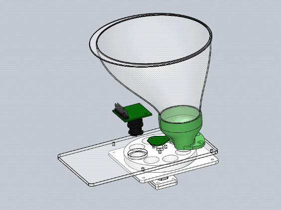
Before we can get to that, however, we need a way to grab the M&Ms one by one. I decided to use a big funnel, such as you would use in a kitchen, to put all the M&Ms into. The bottom of the funnel is open and underneath it a disc rotates. In this disc, there are holes the size of an M&M, and thus the hope is that they would neatly fall into these holes.

It turns out that this is not quite as simple as it seems. Sure enough, if the disc rotates slowly, everything works perfectly. Once things speed up, however, M&Ms start breaking (or the disc just halts due to lack of torque). This is because they sometimes two M&Ms are squished into the same hole in the disc. Remember that I want to sort about 5 M&Ms per second, so rotating slowly is out of the question. Yes, I could enlarge the disc’s radius, but then there would be no way to make the machine small enough to fit into a backpack…
It took a lot of tweaking with various prototypes to get the design more or less working. Turns out that increasing the diameter of the holes in the disc by just 0.5 mm makes a world of difference. Right now, it manages to spit out about 4.5 M&Ms per second, but every once in a while one will still get stuck, and much more often if the M&Ms are not hard (i.e. cold) enough.
Recently, I had the idea to replace the whole selection mechanism with some sort of auger screw (i.e. Archimedes’ screw), but since I’m on my trip, testing that idea will have to wait for a while.
Color recognition
There are two main methods of determining the color of each M&M. The first is using a color sensor, which can be bought for almost nothing on eBay. These sensors work by successively sampling the intensity of reflected light through 3 different color sensors. One drawback is that sampling does not happen at 1 point in time. Thus, if the M&M is moving, that might be problematic. However, I don’t have access to the datasheets right now, so this might be an exaggeration. More importantly though, is that many people seem to have trouble getting consistent results from these sensors, in particular to determine between e.g. red and orange. Because they are so cheap, I went ahead and ordered a sensor anyway, but I’ll only use it as a backup.
The way I want to detect colors is by using a camera. These can be had for 6–15 euro on eBay, depending on which type you order. The main drawback here is that the electronic interface is much more complex. I can attest to this after having tried to interface with at least 4 different types and only managing to get semi-usable images from one of them. Suffice to say that documentation is often severely lacking, and sample code often does not work. The fact that these camera modules often have over 150 32-bit configuration registers does not help matters. Either way, for now I’ve decided to continue on this path.
Because you get an image instead of a single measurement (such as from a color sensor), it’s my hope that by using basic digital signal processing, I should be able to get a close to 100% correct color recognition rate.
In order to comfortably handle the amount of data a camera produces, you need a much more powerful processor than what one generally sees in DIY projects (i.e. by which I mean an Arduino). Sure, it’s possible, but not while simultaneously handling a touchscreen-driven GUI, PID-controlled motors, and a webserver from the same chip. So, for this project I’m using an STMicro STM32F427 (don’t quote me on that though, can’t check it right now).
Because acquiring a color measurement (whether it’s an image or a reflectivity measurement) should take very little time, I have for now combined this step together with the selection step, which you can also see in the render above.
Sorting step
Finally we come to the sorting step, the last “mechanical” part of the design. From what I had seen in others their designs, moving one M&M to one of six possible bins is a slow process. I definitely wanted to avoid doing this, so split this step into two. Of course, the fastest way is probably to use 5 motors that control “doors” over which each M&M passes and selectively letting them drop into those holes (or a pneumatic equivalent). I didn’t want to use that many motors (or a compressor) though. In my design, first the M&M would be assigned to one of two groups, and in the next step it would be dropped into one of three remaining bins.
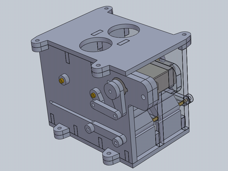
The 1-to-2 design seemed like it would be simple enough so I focused on the 1-to-3 instead. The original design for this was strongly influenced by an idea one of my friends, Frederik, came up with. The M&M would fall in a hole and two parallel paddles would guide it to one of three correct outputs. In order to prevent the M&M from slipping through anywhere, the paddles need to be able to shorten and lengthen as required. This is accomplished by having a thick, hollow upper paddle into which a thinner lower paddle slides. The bottom of the lower paddle slides in a horizontal slot, the top of the upper paddle rotates. This mechanism is created twice, once for each of the two groups into which the M&Ms are first divided. I’m sure the renders and pictures will makes everything more clear.

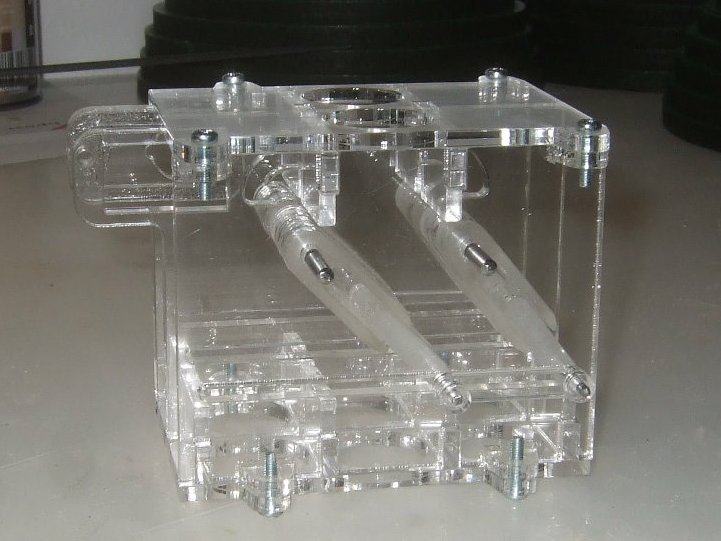
The problem with, and ultimately the demise of, this design is the way I had to fabricate it. I didn’t want to spend hundreds of euros on prototypes, so my main “fabrication” tool at this stage is a laser cutter. Unfortunately, laser cutters don’t cut straight through a material, because the laser beam gets deflected and, more importantly, defocused as it cuts deeper into the material. This meant that the angles of various bearing surfaces weren’t nearly as straight as they should have been, which generated lots of friction in this small design.
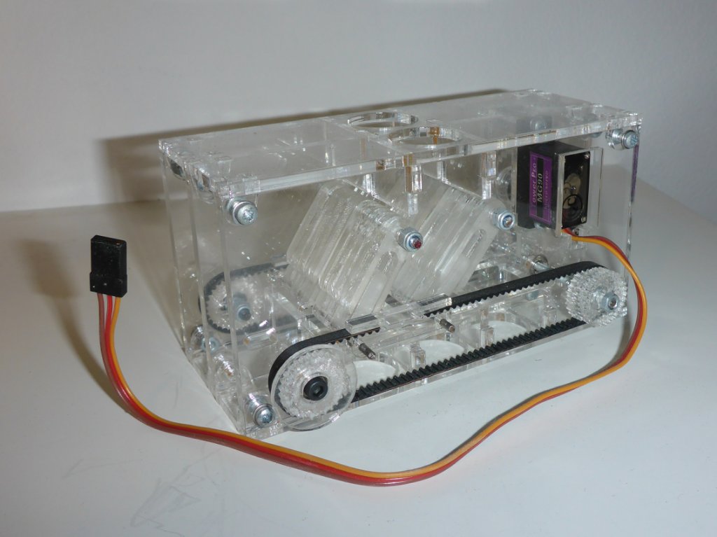
Manually moving the prototype worked, but due to friction it didn’t work with the micro-servos I had on hand. I updated the design to use lots of miniature bearings, and added a gearbox to speed up the movement of the paddles. However, I ran into the same friction-related problem again. On top of that, the design was a nightmare to assemble. Time to search for better options!


Version two of the mechanism was born when I realized one can also use a rotating disc to create a “1-to-3” sorter. However, as opposed to the previous version, in this case the top of the sorter has 3 opening and the bottom only one. The left and right top openings curve towards the center opening in the bottom. And M&M falls into the curved opening in the top and is then guided to wherever the bottom opening is located. By optimizing this some more, you eventually end up with a funnel divided into two parts (one for each of the two groups of M&Ms).

There’s many advantages to this design. First of all, there shouldn’t be any friction, since the funnel can rest of the driving motor’s axis. The funnel is very light, so that shouldn’t pose any problems, and if it does, one can always add an axial bearing on the other side for some extra support and rigidity. It’s also very fast: no matter what bin an M&M needs to end up in, the funnel only needs to be rotated by maximum 60 degrees.
You can make a drawing to verify, but it’s also possible to see this mathematically. One step of the funnel equals 60 degrees (180 degrees / 3). Half a turn equals 3 steps and changes nothing, since the funnel is symmetrical. Therefore, you are basically working in a system modulo 3. Let’s say the funnel is currently on position , and you need to get to position . The number of steps you need to move is such that can never be higher than 1 because of the modulo operation. Fast :)!
So, that solved the sorting problem! The 1-to-2 sorter is build on the same principle, except of making a complete funnel, I use just a pie-sized section and a microswitch as end stop on each sides. An M&M is dropped into the 1-to-2 sorter, passes through a chute and then passes through the 1-to-3 sorter into its final container. The renders and images should clear that fuzzy explanation right up ;).


I created a small test setup to see how fast the 1-to-2 sorter could work. After tweaking my code for less than 5 minutes, I already had something that was able to sort 18 M&Ms per second in the worst case (meaning each M&M would need to be sorted into a different group than the previous one). Great :)!

Frame design
Not much to be said here, really. To keep the frame design flexible, I decided on Misumi HFS5 (20×20mm) extrusions with a rounded corner (i.e. only 2 flat sides). These are set in a rectangle, as pillars, and the individual modules of the design are attached to these pillars using HFS3 (15×15mm) extrusions. Each module uses a baseplate that is 3mm thick, which slides into the HFS3 extrusion. This makes for a very flexible setup and once finished will still allow for the whole design to be encased with a 1mm plate on each side.


Motor position control
Two of the 3 mechanical parts of the design require a servo motor. First there’s the selection mechanism, which needs the servo in order to control rotation speed. As a backup, one could use the camera module to detect the holes on the rotating disc and derive the rotation speed that way. The second servo is required for the 1-to-3 sorting module, which needs to know in which position it is to guarantee M&M drop into the correct bin. Of course, one could also use a multitude of hall- or photosensors, but that just seems silly and very much not extensible.
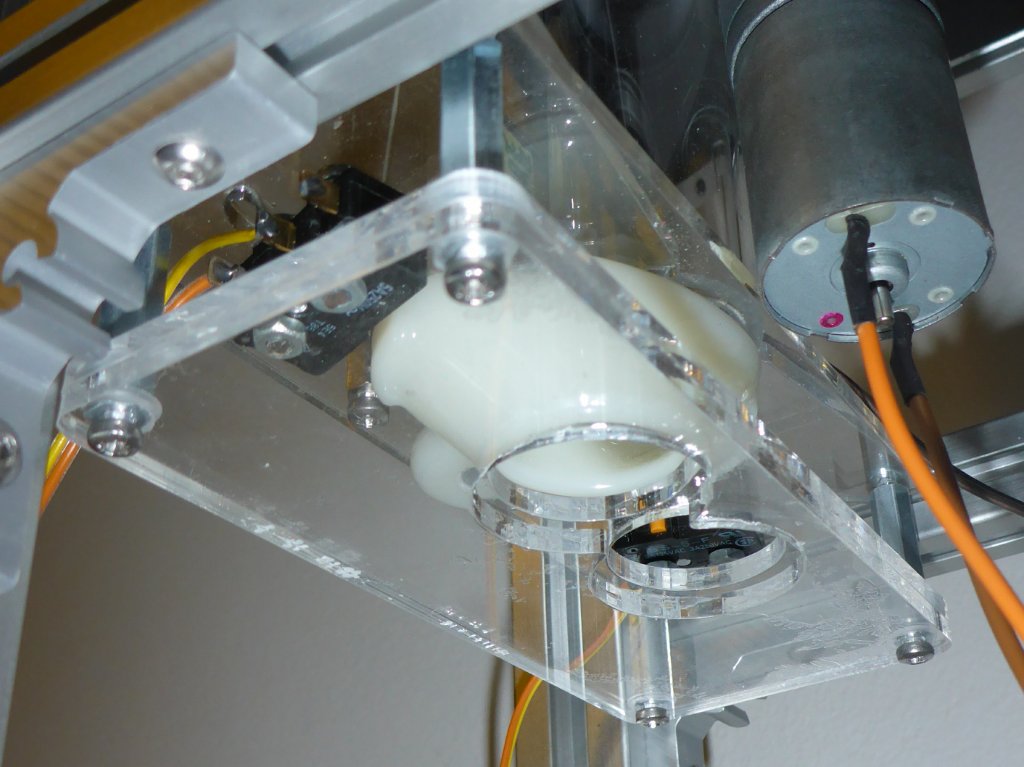
So, servos it is. However, in this case the servos need to be able to rotate in the same direction indefinitely. Such servos can be bought, but the only ones I’ve found are extremely expensive. Luckily, there’s a solution: you can make them yourself by combining a DC motor and an appropriate position sensor. DC motors are cheap and very easy to drive, so that’s already part of the problem solved. An Austrian company, AMS, fabricates specialized hall sensors which detect the orientation of a magnetic field rotating above them, in up to 12-bit resolution. For this to work, you need diametrically magnetized magnets, but in case you’re not picky a regular magnet turned 90 degrees should also do the trick. Best of all, both the chip and the “special” kind of magnets are not particularly expensive. You place the magnet on the motor’s axis and mount the chip above it, some coding later, and there you go: contactless 12-bit resolution digital infinite-turns servo exactly to your design for less than 20 euro!
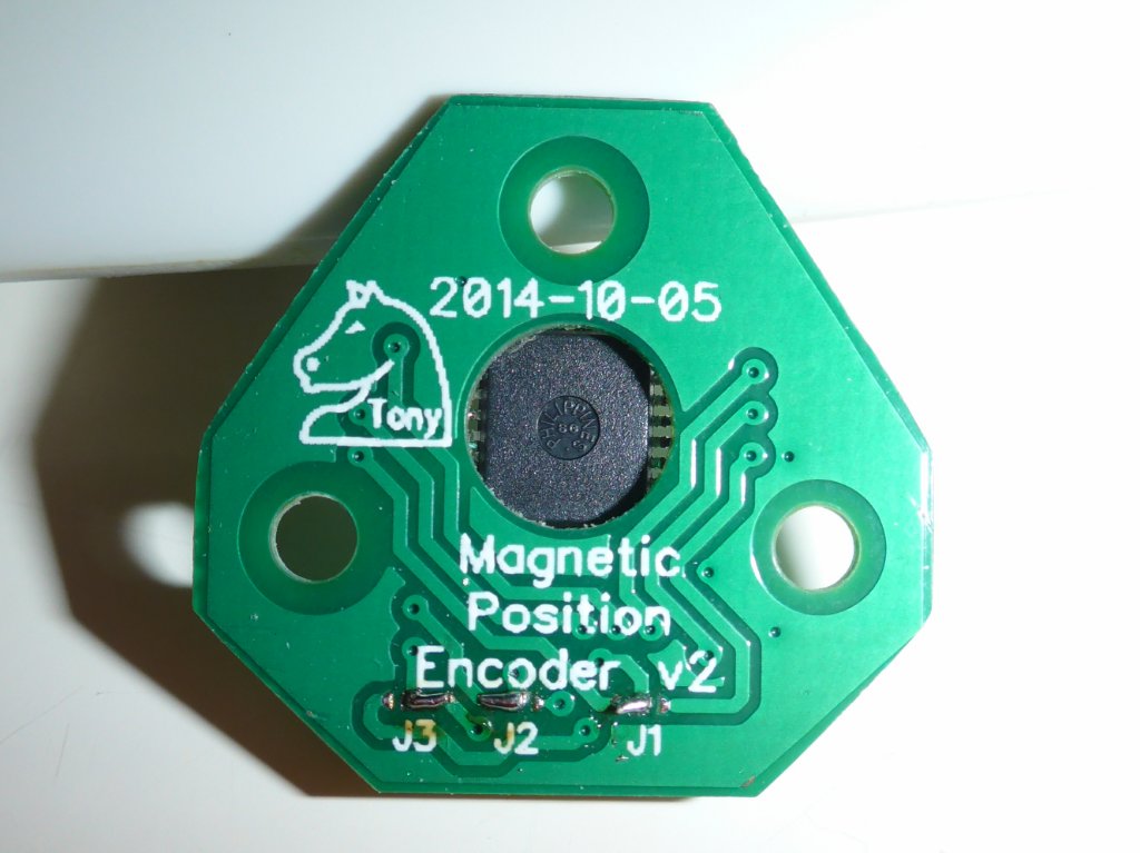
Clearly, getting this chips to work is crucial for my design to work. And unfortunately, this is were it’s currently halted. Despite trying 5 different magnets, 2 PCB designs, both self-written and other people’s code, as well as analyzing the input to and output from the chip with a logic analyzer, I can’t get any meaningful data out of it. I keep hoping to find a silly mistake that I made, but no such luck so far. Once I do get this working, I’m fairly confident that I can get an at least partially functional machine put together quite quickly. Alas, so far nothing…
Remainder of the software
It would be silly to say that once the hall sensor problem is fixed, getting all the rest of the software finished is only a trivial amount of work, but at least it would be easier to troubleshoot problems. Of course, that’s ignoring things such as complex camera modules with virtually no, or outdated, documentation.
What remains to be implemented after the hall sensor problem is fixed, is the following. First of all motor control, which would be PID-based for the selector and 1-to-3 sorter, and motion-profile based for the 1-to-2 sorter. Then there’s the camera interface and image processing. After that, the GUI and touchscreen, preferably with hardware acceleration, which the STM32 chips provide. And finally, the network interface. Oh, and the “glue” to make everything work together of course.
All of the above needs to work in parallel, which would be a nightmare to maintain without a real-time OS. For now, I’ve settled on ChibiOS. I might switch to FreeRTOS though, since that is supported by the official STM32 tools, so it should be easier to get help in case it proves necessary.
Electronics
What I didn’t mention anywhere, is that all of the above also requires a custom PCB. I can use a development board for the individual parts, but in order to use together e.g. the camera module and the touchscreen, a custom PCB is required.
On this PCB, there need to be 3 DC motor drivers, a camera interface and preferably some form of SRAM, the touchscreen interface, an ethernet interface (including all the magnetics), connections for the various sensors, and maybe some extra buttons. So, this will certainly be a handful to design. I’m already looking forward to it ;).
Closing words
As should be clear by now, this project is far from finished. But, like I said, I wanted to get something about it out there, since parts of it have been laying on my desk for so long now.
If you have any comments or remarks, please let me know through the comments section!