Since the first 3D printer I constructed, a variation on the Rostock, only worked so-so, I decided to tear it down and reuse its components for a new printer. In this first article about my new printer, named HAluBot, I’ll go over and explain my design choices and show some renders of the CAD model I constructed.
Core ideas
The main problem I had with my Rostock 3D printer was irregular printhead movement. In a delta 3D printer such as the Rostock, the position of the printhead (in XYZ-space) depends on the position of the carriages on all three delta axes. Therefore, any error in the alignment and position of any of those three delta axes will mess up the printhead’s position on the X, Y and Z axes, not just on a single axis. Although I constructed that first printer out of lasercut parts, they slid together like a puzzle, which made the final construction imprecise, leading to those problems.
Since I do not care to revisit the problems I had with my Rostock, I decided on two core design choices for the new printer design. First of all, it will be a Cartesian printer, i.e. one with three independent axes at 90°. Second, I do not want to have to lasercut huge parts, because those would have to be split up and put together like puzzle pieces, leading to imprecision in the final part. Instead the frame will be build out of aluminum extrusions. This will make it both very strong and precise. Some parts will still be lasercut, out of acrylic, but these will be small and aligned with the help of the extrusions.
What I did like about the delta design was that the printhead could move very fast, because the motors were fixed. In most Cartesian printers, at least one motor always needs to move the printhead as well as another other motor, i.e. an X-axis mounted on an Y-axis. Thus, I decided to design my printer around a CoreXY or H-belt drive system. In such a system, the printhead is fixed to a timing belt which is connected to two fixed motors. If both motors are driven in the same direction the printhead moves on the X-axis, if driven in opposing directions, it moves on the Y-axis. By varying the relative speed and direction of both motors any movement in XY-space can be achieved. The benefit of this system is that both motors work together to move the printhead on two axes, thus very fast movements are possible.
The CoreXY system has a mechanical advantage over a regular H-belt system in that it eliminates torsion forces on the moving carriage. However, for that to work, the belt needs to cross itself at one point. I decided to integrate my XY-drive completely inside the aluminum extrusion, which makes such a crossing impossible. Therefore, I chose to use a regular H-belt system.
The new printer will be named HAluBot, after the H-belt system and the aluminum extrusions out of which it will be constructed.
Build volume
My Rostock’s build volume was more or less a cylinder with a diameter of 23 cm and a height of 24 cm. I want this new printer to have at least that build volume as well. With “go big or go home” in mind, I have chosen to make HAluBot’s print volume at least 30x30x30 cm. Furthermore, it should be able to accommodate at least two extruders. I want to be able to experiment with traditional extruders (i.e. non-Bowden), which require extra space for a stepper motor, and even with two such extruders mounted, the total build volume should still be at least 30×30×30 cm.
Frame design
As stated before, the frame will be build out of aluminum extrusions. This allows me to create a lightweight, very rigid frame, which can be easily bolted together. I’ve chosen to use the 20×20 mm Misumi HFS5 extrusion, since at around 5.5 €/m it’s cheap and Misumi cuts to the exact size required for free. One drawback of using extrusions is that you need to use custom T-nut fasteners. However, Misumi sells their cheapest nuts in packs of 100 for €14 and with non-extrusion designs you often need custom printed parts to hold things together, so all in all it’s not that bad.
The printbed is also designed with extrusions. For this I chose Misumi HFS3. This is a small 15×15 mm extrusion which doesn’t require custom T-nuts, you can use regular M3 nuts, which is a nice bonus.
H-belt drive
First of all, let me explain the working of a H-belt drive system once more. In the image below, the green circles marked M are the two motors. These are mounted in a fixed position, they can’t move. The other two green circles are freely rotating pulleys which can’t move either. The orange circles are bearings which can move between the motors and the pulleys (i.e. up and down in the drawing). A timing belt (in black) is tensioned in the shape of an H between all these. A carriage (in red) is connected to the timing belt in the center between two of the bearings. The orange circles can be bearings because the backside of the timing belt is smooth, i.e. no pulleys required there.
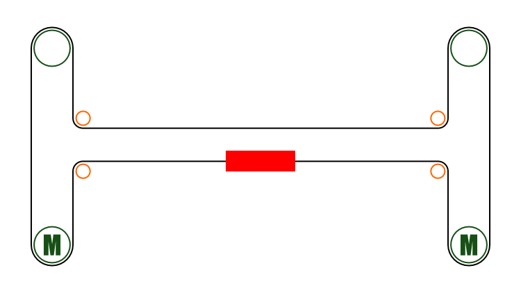
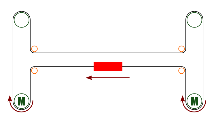
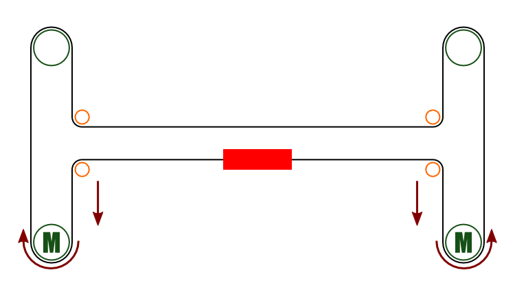
When the two motors move in the same direction, one motor pulls on the “carriage side” of the belt, while the other “pushes” it (i.e. pulls in the resulting slack). Due to this, the carriage will move left/right between the bearings. If the motors move in opposite directions, they both pull the timing belt in the same direction. Therefore, the carriage can’t move sideways, it has to move up/down. The picture below should hopefully make all of this a bit clearer.
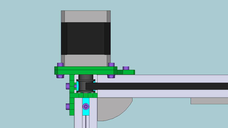
From the very start, I decided to make the drive mechanism as unobtrusive as possible, i.e. the less space it took up, the better. The timing belts I’ll use fit within the slots of the extrusion. And, due to a stroke of luck, the pulleys are more or less exactly the same diameter as the spacing between two opposite slots in the extrusion. So, it is possible to put the drive mechanism completely inside the extrusion, with the two motors mounted on top. The next image shows a render of the motor end of this design. What you see a sideways perspective with the stepper motor on top. As for a color legend: extrusions are light gray, the pulley is dark gray, the timing belt black, fasteners are purple, T-nuts turquoise, and the green parts are laser cut acrylic. The gray triangle is a corner bracket keeping the frame together, the gray bar on the right a linear rail (which I’ll come to later). A piece of acrylic in front has been hidden, in order to make the mechanics visible. The timing belt is not completely rendered for the same reason.
The motor shaft has a 5 mm diameter and supported by an MR85 bearing (8 mm OD, 5 mm ID), which barely fits underneath the pulley and is press fit into a piece of laser cut acrylic. The fixed pulleys (i.e. the top green circles in the images higher up) are designed slightly different. The pulleys I have consist of a central aluminum shaft press fit onto the plastic pulley which has an inside diameter of 8 mm. Furthermore, the HFS5 extrusion have a central hole with the correct size for tapping an M5 thread. Perfect! I will remove the central shaft from two pulleys and glue in two MR85 bearings. These are then slid over and M5 bolt which is threaded vertically into the extrusion. The pulleys will be able to spin unrestricted due to the bearings and should auto-align themselves vertically on the M5 bolt due to the belt tension. A render of this design is shown below. The pulley is rendered as wireframe (in blue), inside you can see the two bearings (orange).
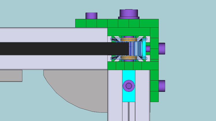
The next part of the drive system is the bearing section (orange circles in the images higher up). These should be able to rotate freely, while partly inside the extrusion slot. The slot is 6 mm wide, so the bearing height should be less. The bearing needs to be partly inside the extrusion, so that the timing belt can stay inside of it. However, the bearing should still be big enough so that the inner face lies outside of the extrusion, otherwise it can’t be mounted on a shaft. After trying out a lot of different bearings (luckily I did all this in CAD first), I decided to use 624 bearings for this, which has a 16 mm OD, 4 mm ID and 5 mm height.
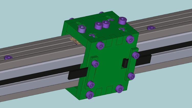
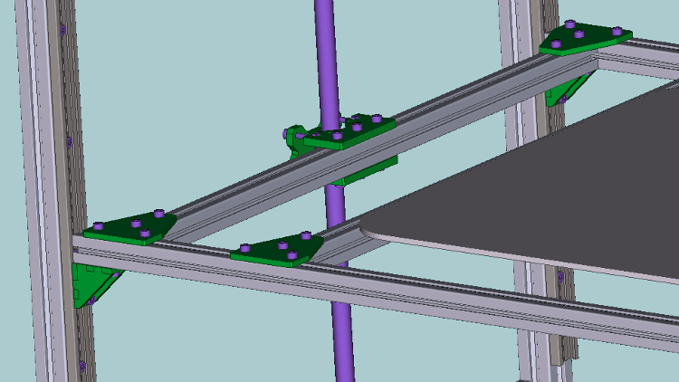
The design is shown below, the green parts will be constructed out of laser cut acrylic. In this render, the Y-axis runs left to right and has a linear rail on the bottom, the X-axis (which can move in the Y-direction) runs towards the bottom-left corner and has linear rails both on top and bottom. The bearings are attached to the X-axis, which will be constructed out of a single length of extrusion. The Y-axis is then the fixed part of the frame between which the X-axis slides. The long M4 bolts will be shoulder bolts.
Linear movement
Of course, all the drive systems in the world won’t do any good if there’s nothing the axes can move on. Early on I decided against using rods for linear movement in this design, for the same reason that I want to put the drive system inside the extrusion: compactness. If I use rods, I will need to mount them either below or above the extrusion, wasting space.
What I want to use instead are linear rails. These are precision mechanics designed exactly for this sort of thing and available down to extremely small sizes (e.g. THK has 2mm wide rails), yet very strong, since they are made out of square stainless steel stock. In this case a 9 mm wide rail would be ideal, since it can be bolted directly to the extrusion, very little space would be wasted. However, they have one big drawback: they are quite expensive. Even from the cheapest supplier a 9 mm rail can easily cost 100 €/m. So, that option is off the table as well.
Enter igus. This company specializes, amongst other things, in all kinds of linear movements. However, they only use special types of plastic for the moving parts. This allows them to fabricate their rails out of aluminum, which is much softer, but also cheaper, than stainless steel. One rail in particular appealed to me: the 17 mm wide DryLin N (NS-01-17). This width is perfect for the extrusion, and the rail plus carriage is only 6 mm high. Best of all, it costs only 15.50 €/m and the carriages are €2.21 each, which is peanuts compared to stainless steel linear rails. I requested a small sample of the rail and a few types of carriages, which igus was very happy to provide. I can’t overstate their helpfulness, they will even call you to help you figure out which parts are best for your design. Fantastic!
I decided to use the NS-01-17 rail everywhere in the design. The DryLin Expert calculator on igus’ website made it pretty clear that using only one carriage per rail was a bad idea, so I will use two on each rail. There’s multiple versions of the carriages available: standard, preloaded (tensioned against the rail for less play), with a play in the Y direction, with play in the Z direction, and finally with play in both Y and Z. Figuring out which works best where will require a bit of experimentation.
Mounting the rails to the extrusion requires low head socket cap M3 bolts (DIN 7984) to prevent the carriages from hitting the bolts. Such bolts can be quite expensive though. Luckily there’s a much cheaper alternative that works just as well: button head hex bolts.
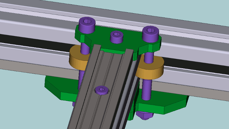
The X-axis rails will be mounted on the top and bottom of the X-axis extrusion, with two carriages in each rail. The Y-axis rails will be mounted on the bottom of the extrusions, hiding them out of sight. For movement along the X-axis I don’t foresee any problems, however, the Y-axis movement might prove a little problematic. Because the rails will be at least 30 cm apart, the slightest unevenness in forces in the Y direction will tend to twist the X-axis, thereby possibly locking up the Y-axis. How big of a problem this is going to be depends on the rigidity of the carriage design. I’ll probably need to experiment a bit to get good results. Shown below is a render of the X-axis moving carriage on which clamps for the timing belt and a part of one of the linear rail carriages (beige on top) are visible. By using longer screws on top and bottom, extra parts, such as an extruder, can be attached to this X-axis carriage.
Z-axis design
So far, I’ve only talked about the X- and Y-axes. The Z-axis, along which the printbed will move up and down, will also move along the same type of linear rails. After modelling multiple possibilities, I decided to use 4 rails, mounted on the inner face of the frame extrusions, in which the printbed extrusions will slide. I’m not quite sure this will work though: the twisting problem that might be a problem for the Y-axis will probably be even worse for the Z-axis. This will no doubt also require a good deal of experimentation to get a working design.
For the drive mechanism, I have decided to use a leadscrew. This is a screw specifically designed for linear movement. The benefits over using regular M8 or M10 threaded stock is improved accuracy and efficiency. I decided on a 10 mm leadscrew with 2 mm pitch (each rotation moves the nut by 2 mm), which costs around 20 €/m on eBay.
The mechanism is pretty simple: the nut is fixed to the moving part and the screw to the frame. The screw is then turned with a motor and as a result the nut will move up and down. An alternative method is to rotate the nut instead, which is often used when the screw is very long. The drawback in that case is that the mechanics are a bit more complex than for a “regular” design in which the screw is rotated. For this first attempt, I decided to use only a single leadscrew, although I’m afraid this won’t quite work out and I’ll need a second screw on the other side of the printbed. Time will tell.
Below is a render of part of the Z-axis platform. The assembly which holds the leadscrew nut is visible in the center, with the leadscrew going through it. On the right is the printbed. Two of the linear rails are rendered on the left. There is a 1 mm space between the HFS3 extrusions and the linear rails, which is why it looks like they are touching in this render.
I’ve seen a lot of printers where the leadscrews are mounted incorrectly, e.g. with the top end unsupported or where the screw pushes down on the motor axis. Although this might not be a problem for the low forces and weights in a 3D printer, I decided to design it correctly from the start.
A correctly mounted screw is most often mounted with one end fixed and one end floating. At the fixed end, the screw is tensioned against an angular contact bearing, to take up any axial forces while still allowing rotation. Part of the screw extends though the bearing and to this end a motor is coupled. Because axial forces are taken up by the bearing, there are no such forces present on the motor, improving its lifetime. At the floating end, the screw is inserted in a regular ball bearing. The screw should be able to slide though this bearing, in order to prevent compression forces on the screw. In order to be able to do all this, both ends of the screw need to be turned down in a lathe: the floating end to the ID of the bearing, the fixed end partly to the ID of the bearing and partly to a smaller ID for the motor coupler. Finally, part of the fixed end should be threaded to allow it to be tensioned against the angular contact bearing. Again, probably overkill in this case, but it can’t hurt either.
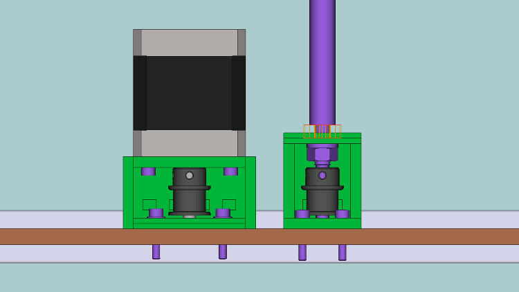
In order to save some vertical space, I did design one part differently from the method explained above. Instead of directly coupling the motor to the screw, a timing belt is used. This allows me to mount the motor face down inside the frame and reduces the printer’s height approximately 5 cm. Below is a render of this design. You can see the motor mount next to the fixed end of the leadscrew. They are mounted on a plate which will be at the bottom of the printer. The motor axis is supported by a tiny MR85 bearing seated inside the acrylic mount. The angular contact bearing is rendered as a wireframe, so you can see the stepped radius of the leadscrew, necessary to tension it against the bearing. The timing belt between the two pulleys is not rendered.
Extras
One extra feature I want is space to mount filament spools, so I don’t need to have extra spool holders taking up space on my desk. For now, I decided to use four short sections of extrusion mounted on the opposite side of the leadscrew. The spools won’t interfere with the hotend nor the printbed. If it turns out a second leadscrew is required on this side of the frame, I’ll probably create some lazy suzan-style spool holders on top of the frame, a great idea from the folks that made the Quantum delta printer.
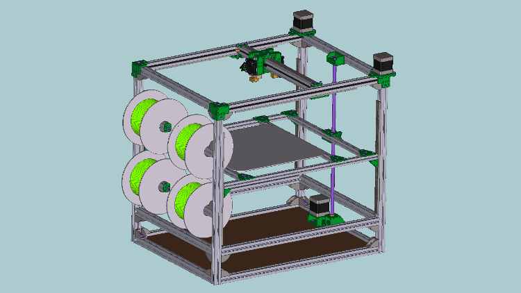
Complete design
The design of all the acrylic parts used for joining all the parts together is finished, and most required parts have been ordered from igus and Misumi, the remaining I got on eBay. Due to the size taken up by a non-Bowden extruder, the leadscrew, and the electronics on the bottom of the frame, the final frame size is 43×56×52 cm, quite a bit larger than the printbed. Below is a render of the complete design. Stay tuned for the next article in this series, which will no doubt contain a lot of new and improved designs.