In the summer of 2012, I stumbled upon the fantastic delta 3D printer by Johan Rocholl, the Rostock. Until then, 3D printers didn’t really interest me, but the Rostock looked so nice that I couldn’t ignore it. So I decided to build a derivative version myself, and started designing.
Introduction
The way most hobby, and many professional, 3D printers build models is with a technique called fused deposition modeling (FDM). Models are build up by pushing molten plastic through a small nozzle and depositing it on top of previously laid down plastic. Due to its high temperature, the newly deposited strand of plastic will fuse to the underlying one. By laying down layer per layer, a complete 3D model is formed.
In order to generate the layers (and thus the movement commands for the printer), a so-called slicer program is used. For the end user, slicing requires no more than loading a 3D model and telling the slicer the required layer height (along with some other, fixed printer dependent settings). Different programs can generate quite different code though. The better ones will try to optimize the path the printer’s hotend follows, so that it doesn’t make large jumps or cross over multiple outside edges of the model.
Delta principle
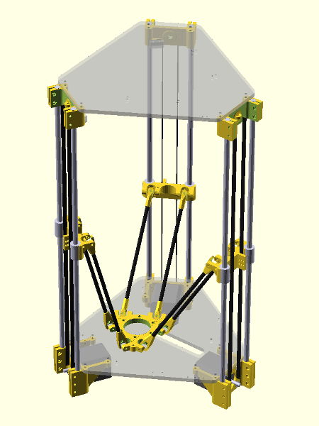
The Rostock was, at the time of its presentation, significantly different from any other printer out there. Instead of a Cartesian printer, in which all 3 axes are perpendicular to each other, it is a delta printer which uses six vertical rods. In this delta design, the six rods are grouped per two and those three groups are arranged in an equilateral triangle. Each pair of rods is connected to a central carriage with two arms. Normally, the central carriage would have six degrees of freedom: three of translation, and three of rotation. However, by fixing the pairs of arms parallel to one another, the three rotational axes are restricted, forcing the central carriage to stay parallel with the print bed. The central carriage is moved in XYZ-space by moving the carriages on the vertical rods up and down. Here is a render of what a delta 3D printer looks like in general:
That’s still quite abstract, so here is the video that inspired me to building my own delta printer. It’s one of Johan’s first Rostock prototype:
The main mechanical advantage a delta printer has over a Cartesian one is the lightweight central carriage. In most delta 3D printers, only the printing hotend is mounted to the carriage, so the motors have to move very little weight around. This makes it possible for delta printers to attain very high movement and printing speeds.
Of course there’s also a few drawbacks. For example, quite a bit of vertical space is lost due to the diagonal arms (those going to the central carriage). Depending on the printer design this can easily be 25 cm. Another problem with delta printers is that mechanical problems can be harder to track down and fix than on Cartesian printers, because the XYZ-axes are each dependent on all three delta axes.
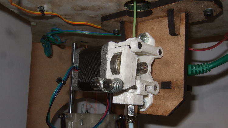
Contrary to most other 3D printers, the Rostock does not move the motor used to extrude plastic filament. Instead, the extruder is mounted stationary and the plastic is fed to the hotend using the Bowden cable principle, whereby the plastic filament is pushed to the hotend through a PTFE tube. Getting good results with such a filament drive system requires a bit more work than with a non-Bowden extruder, but, once dailed in, the print quality is pretty similar.
Design
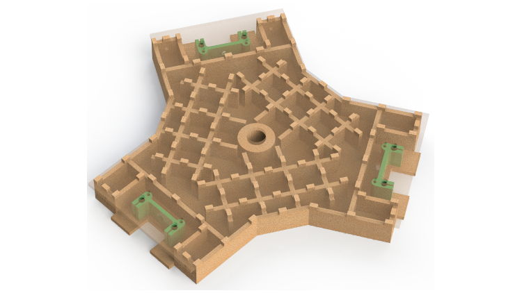
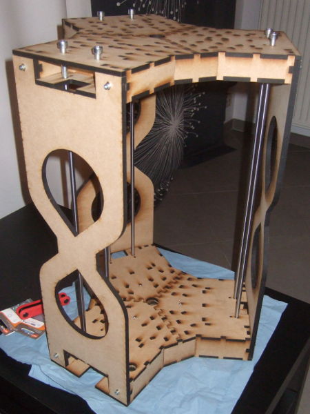
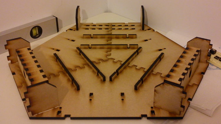
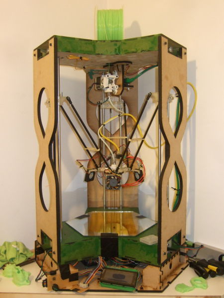
Johan build his frame out of plywood, held together with zip-ties. Since I wanted a printer that wouldn’t look out of place in my living room, I decided to design my own custom frame. Luckily, I have access to a laser cutter, so I didn’t have to keep the shape of the frame constricted to something that would be easy to construct manually. I designed my frame based on a hexagon shape, which fits with the delta theme. In order to make the frame as sturdy enough, both the upper and lower frame are build as a torsion box out of 6 mm thick MDF. Here’s a render for the top frame torsion box, the green pieces are 3D printed parts:
The bottom one is more or less the same, with some extra holes for wiring to pass through. These two parts are then held together with three 9 mm thick pieces of MDF, as well as with the six 8 mm thick vertical rods. A render of my original design for the complete frame is shown below. The green hexagon shape at the bottom is a glass plate on which to print.
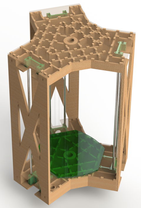
In order to reduce the printer’s footprint, and to make use of the lost vertical space at the top, I decided to mount the extruder on the bottom of the upper frame. The plastic filament is fed into the extruder through the hole in the top frame.
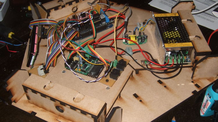
I chose to use a RAMPS board to control the printer. To house all the electronics, a frame was designed on which the printer could stand. In order to simplify setup and prevent wrong connections, I used networking cable (CAT5e/CAT6) for the interconnection between the main electronics board and the extruder, endstops and hotend electronics. This required 16 connections, so I used two cables.
Putting it all together
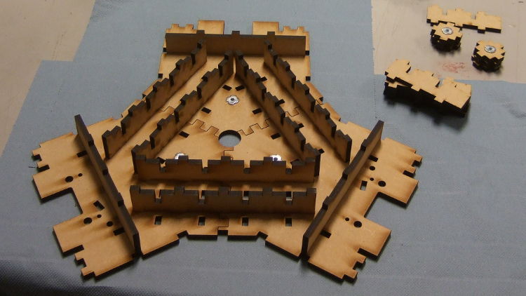
The torsion box design was, in hindsight, extremely over-engineered and required a lot of parts. Due to the size of the frame, it couldn’t be lasercut it in one piece, so each part of the frame was created out of three sections which slid together like a puzzle. The internal reinforcement braces of the torsion box keep these three parts together.
Once the top and bottom frames were glued, the frame could be put together and started to look more or less like the render. In an effort to make the frame look a bit nicer, I filled all the gaps with MDF filler and spray painted it green. Unfortunately, the difference in structure between the MDF (which soaks up paint like a sponge) and the filler (which doesn’t), kind of ruined appearance of the paint coat.
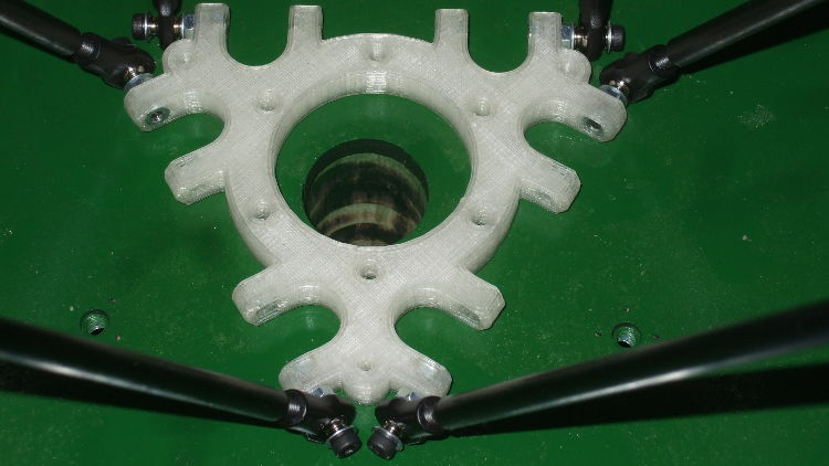
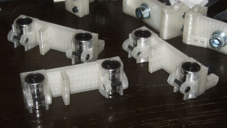
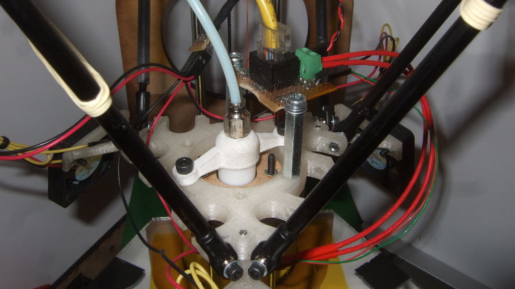
In order to lose as little of the smooth rod length due to mounting as possible, the ends of the 8 mm rods where drilled out and tapped to M6 on the inside and I had the ends of a bunch of M8 bolts turned down to M6. That way, the complete length of the smooth rods can be used for linear motion and the printed parts clamp the M8 bolts. For the universal joints connecting the diagonal arms to the frame and central carriage, I used Traxxas 5347 ball joints, instead of printed joints. The diagonal arms were not printed either, I constructed them out of carbon fiber rods, into which I epoxied M4 bolts to screw the joints onto.
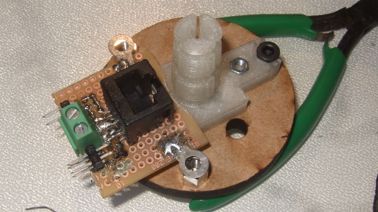
I had the required plastic parts printed by someone in the UK and a friend at work. Most other parts I bought on eBay (power supply, screws, electronics, …). Some parts took up to 5 weeks to arrive from China and often I would find out that I needed some extra parts for this or that. During the time spend waiting I put together an LCD controller board, an SD card reader and an adapter board to connect them to the controller. Furthermore, a few small adapter boards where made to connect the networking cables between the main electronics board, the hotend and the extruder.
Since it took weeks and weeks until I had all parts, the printer was put together bit by bit during a timespan of almost six months. During this time, a few problems reared their head, such as a malfunctioning extruder design and a few fried stepper drivers. Fixing the stepper drivers was just a matter of buying new ones, the extruder was replaced by the Airtripper v3. The most annoying part of the assembly was no doubt connecting the moving carriages to the motors. Initially I planned to use high-strength Dyneema fishing line for this, but due to the way the frame is constructed, tensioning the line proved to be almost impossible. In the end I gave up on the idea and switched to GT2 timing belts and pulleys.
In the meantime I also constructed the stand to house the electronics and support the printer. This frame was even larger than the printer and was thus also constructed using the same “puzzle pieces” technique used for the top and bottom torsion boxes The electronics were mounted on removable plates. The only thing that wasn’t finished was creating panels for the LCD and user interface.
With all that done, the printer construction was more or less finished. Below are some pictures of it in its final state.
Printing
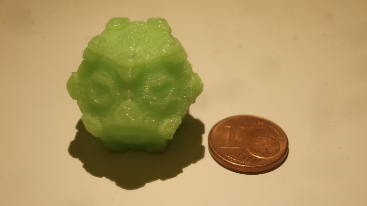
As firmware I initially used Repetier, but didn’t like the LCD layout, so I switched to Marlin. Calibration was pretty straightforward, I used this guide as a starting point. With everything dailed in, I first did some 2D (drawing) tests, which all came out more or less perfect. Time to test actual 3D printing! The first object, a 20mm calibration cube, had near perfect dimensions (19.95mm according to my calipers). So did the next two objects, all of which where sliced with Cura.
Although the objects printer with the Cura-generated code where very nice, the movement code (G-code) made my extruder sound like it was dying. I must have setup something wrong in Cura, although I couldn’t find out what, G-code inspection didn’t make me any wiser either. The Cura code somehow lead to the the extruder repeatedly grinding part of the filament, which made those horrible noises. Strangely enough, this seemed to have little, if any, effect on the resulting print quality. Code generated by Slic3r didn’t have this problem, but the resulting prints weren’t that nice.
Eventually I tried printing larger objects, which is when problems started to become obvious. Due to the way the frame was put together (out of puzzle-like pieces), the diagonal arms all had a slightly different distance from the printer’s center. This made it impossible to get the hotend to move perfectly parallel to the printbed. At certain locations, the hotend would move upwards by up to 1 mm, leading to failed prints. No matter how much I tweaked and debugged, I couldn’t find any way to fix this. The only way to get rid of it, was to completely rebuild the frame. However, unless all parts were cut in one piece, the same problem would likely arise again.
Conclusions
Designing and building my first 3D printer was certainly a big learning experience, especially the mechanical part. The biggest drawback compared to Cartesian printers is without a doubt the dependency of XYZ-movements on all three delta axes, and the resulting problems if those delta axes are not setup exactly identical. In a Cartesian printer, you can generally fix and improve each axis independent from the other two, which is just not possible with a delta.
I find there are three advantages a delta has over a convential 3D printer. First of all, its printable area is almost equal to its footprint, for many Cartesian printers the X and/or Y dimensions can be up to 25 cm longer than the printable distance for that axis. Second, there is the possibility for very fast print speeds, although some Cartesian designs, such as a Replicator2, can match deltas. Finally, a printer takes up space on your desk and deltas do that in style, they just look really cool.
In the end, due to the mechanical problems the printer has, I decided to scap this design and work on a new and improved printer. However, that’s a story for another post.