One minor annoyance when programming microcontrollers in-circuit, is that often quite a bit of PCB space is lost due to the programming connector. Furthermore, when you have to program many chips, repeatedly reconnecting the programming cable quickly becomes a chore. So when I found an article about constructing a programming pen that would help solve both of these problems, I decided to build one for myself.
The idea
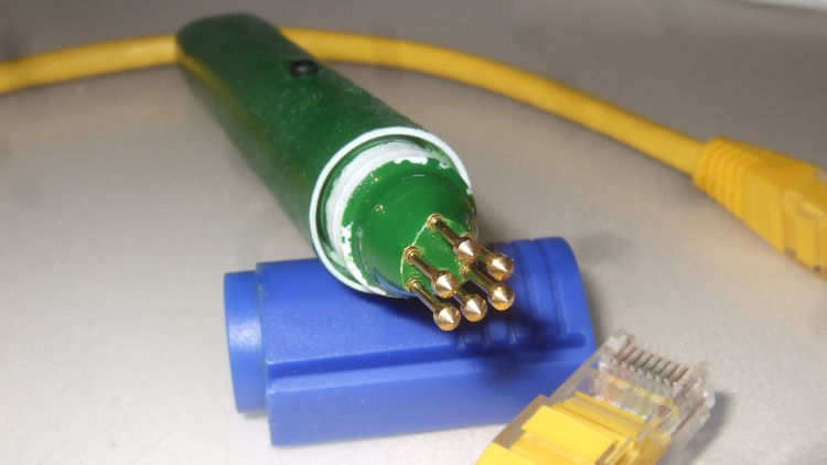
The article that I am referring to is by Mike Harrison. The idea is twofold: first of all, instead of using a cable to connect directly to the board during programming, pogo pins are used. These are small metal tubes with a removable spring-mounted head inside. There’s various types of heads available, such as needle-points and 90° cones. Most microcontrollers (e.g. Microchip PIC, ARM Cortex-M, TI MSP430, …) require a maximum of 6 connections for programming. By using 6 pins arranged in a D shape, you get a footprint that will only fit one way. The pogo pins are build into a pen which is then pushed onto the board while programming the microcontroller.
Which brings us to the second part of the idea: changing the programming header on your PCBs. These get replaced by 6 SMD or though hole pads arranged in the same D shape. Though hole pads are generally easier, since they allow the pogo pins to latch into them. You can put the pads as close together as you want, I opted for a standard 2.54mm distance, so that I could use my pen on prototyping boards as well as on custom PCBs. Even which such a relatively large spacing, the footprint with through hole pads still fits underneath an LPQF-48 package (7×7mm), although in that case the pads should have a maximum diameter of 0.7mm and the holes 0.3mm. For smaller footprint layouts you should use pogo pins designed for 1.27mm spacing.
Building it
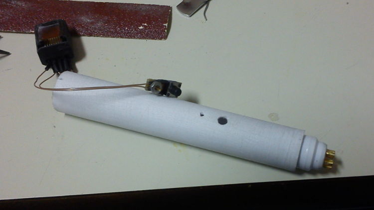
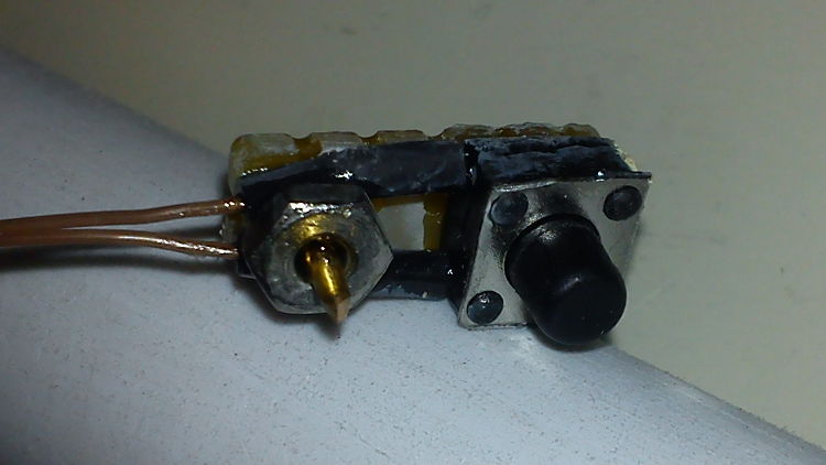
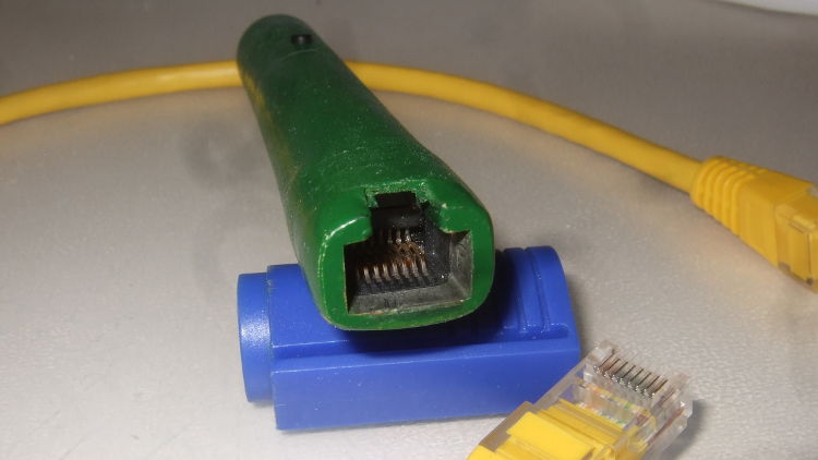
Just like Mike, I chose to incorporate a button into the programming pen. This could be connected to a PC to have it start the programming routine when pressed. Most of the build is the same as Mike’s. The pogo pins are pushed through and soldered onto a triple stack of PCBs to keep them rigid. The pushbutton is glued to a strip of prototyping board which is kept in place inside the pen with some copper rod and an M3 nut acting as a spacer. One thing that I did do differently, was using an RJ45 network jack for the connection between the pen and programmer. An RJ45 jack has exactly 8 pins (6 for programming, 2 for the button), fits the cable only one way and locks onto it, and network cables are cheap and available in all lengths. For the housing I used a permanent marker. You can see a picture of the build in progress and of the pushbutton contraption below.
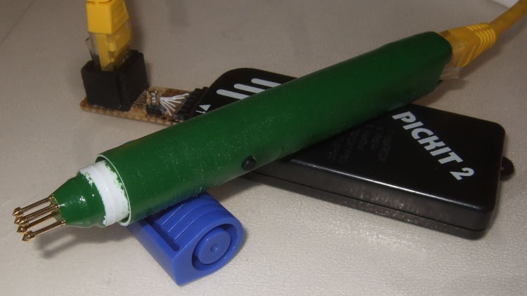
Once I verified that there were no loose connections, I used epoxy clay (Milliput) to fill the gaps around the RJ45 jack and the pogo pins. Next a piece of metal rod was put into the head of the pen in order to improve the feel and to balance it out. It was then stuffed with as much epoxy clay as possible in order to keep everything in place. Finally, I gave the pen a few layers of paint. The result is shown below.
Because I use the RJ45 jack, a small PCB is required to convert between the jack and whatever header the programmer uses. Below is an image of the complete setup with a Microchip PICKit2 programmer. The whole assembly is very convenient and works flawlessly.